![]()

|
Site home page Get alerts when Linktionary is updated Book updates and addendums
Get info about the Encyclopedia of Networking and Telecommunicatons, 3rd edition (2001)
Download the electronic version of the Encyclopedia of Networking, 2nd edition (1996). It's free! Contribute to this site Electronic licensing info
|
LANE (LAN Emulation) Related Entries Web Links New/Updated Information Note: Many topics at this site are reduced versions of the text in "The Encyclopedia of Networking and Telecommunications." Search results will not be as extensive as a search of the book's CD-ROM. LANE was defined by the ATM Forum in 1995 as a way to allow legacy networks such as Ethernet, Token Ring, and FDDI to use an ATM network as backbone connections. In July of 1997, the ATM Forum ratified an enhanced LANE specification called LANE 2.0, which adds support for QoS and other necessary features. Integrating ATM with legacy LANs is not easy. Keep in mind that ATM is a connection-oriented technology. It requires that virtual circuits exist between source and destination before any data can be sent. Data is transmitted in fixed-length cells. Legacy LANs transmit data in variable-length frames over a shared connectionless network. What LANE does is automate SVC (switched virtual circuit) setup across ATM networks for LAN clients. Before LANE, administrators had to manually configure PVCs (permanent virtual circuits) between hosts. Another thing LANE does is map MAC (Medium Access Control) addresses to ATM addresses. It also defines a scheme for encapsulating higher-level protocol datagrams into ATM cells and delivering them across the ATM backbone. Since LANE emulates layer 2 protocols (data link layer), it can transport higher-layer protocols such as TCP/IP and SPX/IPX without modification. This allows existing LAN applications to be used without change. They don't need to know that the underlying network is cell-based rather than frame-based or that it uses virtual connections rather than a connectionless scheme. Since LANE operates in layer 2 (the MAC layer), it is limited to creating bridged networks (and not routed networks) over the ATM switching fabric. You can create multiple ELANs, but if you want clients in those ELANs to talk to each other, you'll need to implement external routers. This external router is often called the "one-arm router." MPOA (Multiprotocol over ATM) is a related technology that provides inter-ELAN routing directly on the ATM network so that separate routers are not needed. MPOA adds a cut-through routing service that allows clients on different VLANs to connect with one another using the routes learned by the MPOA routing service. MPOA is derived from LANE. The problem with LANE is the requirement that traffic go through an external router when the underlying ATM network is fully capable of creating a direct connect between two devices connected to different VLANs. MPOA adds this capability. LANE Configurations A LANE configuration consists of a number of special servers and processes that help end systems obtain SVCs across the ATM networks. LANE also gives the ATM network the ability to simulate the broadcast nature of LANs. Because ATM is connection oriented, it does not have the ability to broadcast to every end system, so LANE adds this functionality. The three servers are described below. Note that these "servers" are really processes that can be located on the same physical piece of equipment:
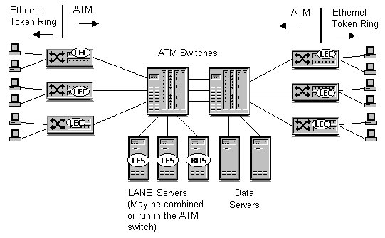
The final piece in the LANE configuration is the LEC (LAN emulation client). The LEC is responsible for interfacing between the LAN interface (Ethernet, Token Ring, etc.) and the ATM network. The LEC process usually runs in a switch, but it may also run in a router or any other device that has an ATM interface. The LANE configuration is pictured in Figure L-1. The typical scenario is to connect an Ethernet LAN to an ATM edge device such as a switch, which has Ethernet ports on one side and ATM uplinks on the other side. Also note that the LES, LECS, and BUS may be integrated into a single server or may run in individual servers. Also note that data servers are connected directly to the ATM backbone.
Figure 1: LANE configuration As mentioned, an ATM network can support multiple ELANs, but you cannot mix different LAN types (Ethernet, token ring) in the same LANE network. Each ELAN acts like a broadcast domain and is managed by a LES and BUS process. The LECS keeps track of each ELAN and LES/BUS combination in its database. Keep in mind that LANE does not provide routing, so ELANs can only communicate with other ELANs by going through external routers or bridges. When a LEC first starts up, it must join an ELAN. The process of joining an ELAN is outlined below. Assume that the LEC device is an Ethernet switch with an ATM uplink that supports LANE, and that the network consists of multiple ELANs:
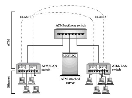
Once the LEC has joined, it can begin participating in the emulated LAN. Assume that a workstation attached to the LEC-enabled switch wants to connect with a server. The packet arrives at the ATM/LAN switch where the LEC reads the destination MAC address. The LEC looks in its own internal table to see if it has an ATM address that corresponds to the MAC address. If not, it contacts the LES over the VCC in order to resolve the address. Usually, the LES has already obtained the MAC addresses of each of the hosts attached to LECs, but if doesn't know an address, it will attempt to discover the address by asking other LEC clients and using the BUS if necessary. Once the corresponding address is discovered, it is returned to the requesting LEC. The LEC then sets up a connection to the destination and begins the process of fragmenting frames into cells and forwarding them across the connection. LANE builds multiple ELANs (emulated LANs) across the same ATM network. An ELAN is a VLAN (virtual LAN) over an ATM network. However, it is defined at the MAC layer while VLANs may be defined in a variety of ways (e.g., by MAC or IP address), including by protocols. Figure 2 illustrates how this works. Note the following:
Figure 2: Virtual LANs in the LANE environment
As mentioned, routers are required to move packets from one emulated network to another. As always, moving packets through a router is inefficient, especially when you consider the fact that the underlying ATM network can provide a direct virtual circuit between two end nodes, even if they are on different ELANs. The LANE specification does not accommodate this, but the MPOA (Multiprotocol over ATM) topic does. Note: Shortcut routing techniques can be a security risk since they bypass router security filtering techniques. LANE 2.0 LANE 2.0 adds QoS features and provides support for multicasting. Additional enhancements include the ability to multiplex multiple emulated LANs over a single ATM virtual circuit. LANE 1.0 sends traffic using the UBR (unspecified bit rate) service, which does not guarantee any bandwidth. UBR and other ATM services are discussed under the ATM heading. What LANE 2.0 adds is support for the other service classes:
Of course, these services must be requested, which means that end systems must be ATM aware in order to take advantage of them. Switches must also be LANE 2.0 aware. Additional information about LANE version 2.0 may be found at the Web sites listed on the related entries page. Copyright (c) 2001 Tom Sheldon and Big Sur Multimedia.
|