![]()

|
Site home page Get alerts when Linktionary is updated Book updates and addendums
Get info about the Encyclopedia of Networking and Telecommunicatons, 3rd edition (2001)
Download the electronic version of the Encyclopedia of Networking, 2nd edition (1996). It's free! Contribute to this site Electronic licensing info
|
Fiber-Optic Cable Related Entries Web Links New/Updated Information Note: Many topics at this site are reduced versions of the text in "The Encyclopedia of Networking and Telecommunications." Search results will not be as extensive as a search of the book's CD-ROM. This topic is presented in its entirety with illustatations as a sample topic. Fiber-optic cable employs photons for the transmission of digital signals across a strand of ultrapure silica (or plastic in some cases). Optical systems operate in the infrared light range. Photons pass through the cable with negligible resistance. The silica is so pure that, according to Michael Coden of Codenoll Technologies Corporation, a 3-mile-thick window made of the purified silica would give you the same view as a 1/8-inch-thick glass window. As optical system requirements increase, the purity of the cable becomes even more important. The best cable from Corning and Lucent is free of all but the smallest trace elements of iron and other metals, as well as hydroxyl ions, which are present due to water molecules in the cable. A fiber-optic cable guides light from end to end. A signal is injected in one end by an LED (light-emitting diode) or by semiconductor lasers. LEDs can generate signals up to about 300 Mbits/sec. Lasers can generate signals in the multi-gigabit/sec range. LEDs are used for short-distance optical links such as enterprise backbones while lasers are used for longer distance networks. Lasers are also capable of the higher power levels needed for long-haul backbone links. Lasers produce light in "windows" of the near infrared range as listed in the following table. A window is an infrared range that is optimized for optical transmissions. The ITU recently defined the following spectral bands in order to clarify the terminology that is used for fiber-optic systems. These definitions are meant for classification purposes only.
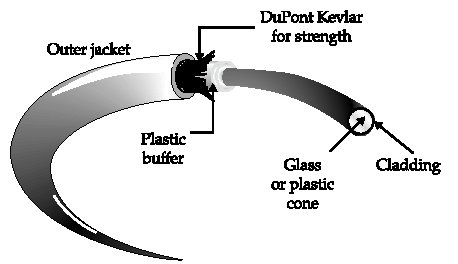
Figure 1 illustrates the structure of fiber-optic cable. The core is the transparent silica (or plastic) through which the light travels. The cladding is a glass sheath that surrounds the core. The cladding acts like a mirror, reflecting light back into the core. The cladding itself is covered with a plastic coating and strength material when appropriate.
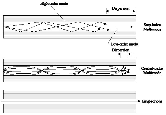
Figure 1 Figure F-2 illustrates the different paths that light will take through a fiber cable, depending on the type of cable. If the core is wide and there is a sharp transition between the core and the cladding, high-order rays will follow reflected paths while low-order modes will follow straighter paths. This causes some of the rays to arrive at the source at a different time-a phenomenon called modal dispersion, as discussed later. Dispersion limits cable distance. Graded-index cable can help resolve the problem, or a small core can be used as in the single-mode cable. An animation that demonstrates the way that light travels through fiber cable is at the Bell Labs Web site given later.
Figure 2 Plastic core cable is used for short-distance applications, such as airplane wiring and wiring for some buildings. The remainder of this topic covers silica-based fiber-optic cable. Silica cable is categorized as either multimode cable, which is used for short-distance connections (LANs, campus networks, and short-distance metro networks), or single-mode cable that is used for long-distance (cross-country networks and intercontinental submarine links). The light source for the former is typically an LED, while the light source for the latter is a laser. Long-haul fiber-optic cable is often bundled with anywhere from 100 to 800 fibers per cable.
Cable specifications list the core and cladding diameters as fractional numbers. For example, the minimum recommended cable type for FDDI (Fiber Distributed Data Interface) is 62.5/125-micron multimode fiber-optic cable. That means the core is 62.5 microns and the core with surrounding cladding is a total of 125 microns. The cladding diameter must be the same when joining cables because connectors typically use the cladding diameter as a guide for aligning the core.
The ITU has defined a series of recommendations that describe the geometrical properties and transmissive properties of multimode and single-mode fiber-optic cables. The four most important recommendations are listed here:
G.655 is the latest development in fiber-optic cable. In particular, G.655 is optimized for WDM and long-distance cable runs such as submarine cables. It uses dispersion to advantage. Dispersion can help reduce an effect called four-wave mixing (FWM), which occurs in DWDM systems when three wavelengths mix in such a way to produce a fourth wavelength that overlays and interferes with the original signals. With DWDM, a single fiber can potentially carry thousands of lambda circuits. A lambda is a specific subwavelength of light within one of the windows of light. It provides all the capabilities of an individual circuit. Lambdas are set up using frequency division multiplexing. Think of each lambda as a specific color of infrared light transmitting at 10 Gbits/sec or more. An optical multiplexer divides the available spectrum on the cable up into many individual lambdas. For example, the Avanex PowerMux can put over 800 channels on a single fiber with spacing between channels of 12.5 gigahertz. With the potential of thousands of lambdas per fiber, it is practical for carriers to lease entire optical wavelengths to businesses. See "Optical Networks." An alternative to DWDM are new optical modulation techniques that boost the capacity of existing cables. Kestrel Solution's Optical FDM combines FDM (frequency division multiplexing), DSP (digital signal processing), and optical modulation to improve performance on existing fiber cables, especially in metropolitan areas where low-quality fiber has been installed (due to short distances) and in SONET systems. Optical FDM gives full access to the total bandwidth of the cable. Cable Performance Characteristics Fiber cable has certain characteristics that limit its performance. Cable from different manufacturers may exhibit variations in these characteristics. The primary performance limiters are attenuation and dispersion. Attenuation, EDFAs, and Raman Amplifiers Attenuation is signal loss over distance. Think of the light pulses as loosing their energy and flattening out as they travel down the cable. High attenuation will result in errors at the receiver. Attenuation is not a problem for metro-area networks, but it puts distance limitations on long- haul backbone networks. Three types of devices may be used to overcome attenuation:
EDFAs are crucial to WDMA systems because a single amplifier boosts all the wavelengths simultaneously. With older electrical regenerators, one regenerator is required for each wavelength, meaning that an entire stack of regenerators is needed at each regeneration point. The 1,550 range (C band) is often called "erbium window" because the energy level of erbium ions is close to the energy level of photons in the C band. Through the process of stimulated emission, erbium can be coaxed into releasing energy that amplifies light in the C-band. The process is as follows. The EDFA amplifier pumps photons into the erbium-doped cable. Erbium atoms absorb photons, which cause electrons to jump to a temporary excited state. When an electron decays, it releases a photon that is absorbed by the signal photons. Thus, the optical signal passing through the cable is amplified without any electrical conversion. Dispersion Another characteristic is dispersion, which is the broadening of a light pulse as it travels down the cable. Excessive dispersion will make a signal difficult to read by the receiver. When an LED or laser sends light into a multimode fiber, a range of wavelengths of light is present. Some of those wavelengths travel at different speeds than others. The effect is to distort waveforms, which can cause errors in reading the signal at the other end of the cable. Graded-index cable is designed to minimize the delay of the slower wavelengths. There are four types of dispersion:
G.652 cable, used in most commercial systems, takes advantage of the 1,310-nm window where chromatic dispersion is minimized. This window is often called the zero-dispersion point-it is the range where chromatic dispersion is minimized because the waveguide dispersion cancels out material dispersion. Long-haul carriers, on the other hand, have higher bandwidth and distance requirements, so G.653 and G.655 "dispersion-shifted" fiber operating in the C band is preferred. The C band is used for DWDM systems, which support many closely spaced channels at data rates of 10 Gbits/sec and higher. Two other bands are now being used to boost capacity and distance: the 1,460 nm to 1,530 nm S band and the 1565 to 1625 L band. A newer approach employs soliton technology, which can be used to create a cable system that stretches nearly halfway around the world. See "Soliton." Note that it is possible to support DWDM on many older fiber cables. Standard single- mode fiber will support DWDM at lower data rates. Some older dispersion-shifted fibers were not able to handle DWDM, but these cables may be made to act like nonzero dispersion cable by using wavelength above and below the 1,550-nm window. Corning and Lucent are the major providers of long-haul cable. Lucent's TrueWave and AllWave cables are made of single-mode nonzero dispersion fibers that support all the wavelength windows. TrueWave is specifically designed for optically amplified, high-powered long-distance DWDM networks operating in both the C band and the L band. Both cable types are manufactured with a patented purification process to remove water molecules in the core, thus allowing wider spectrum usage. Corning's LEAF is a single-mode NZ-DSF fiber designed for DWDM systems. It combines low attenuation and low dispersion with an effective area that is 32 percent larger than non- NZ-DSF fiber. This allows more power to be pumped into the network over more channels without nonlinear effects that create noise, distort signals, and degrade performance. It can operate at 10 Gbits/sec or higher using high-output-power EDFAs. Corning's MetroCor fiber is a single-mode NZ-DSF cable optimized for short-distance metropolitan usage. It does not require the powerful lasers that are required in the long-haul environment and so helps reduce the cost of implementing metropolitan fiber networks. For more information about metropolitan optical networks, see "FTTH (Fiber to the Home)," "MAN (Metropolitan Area Network)," and "PON (Passive Optical Network)." Copyright (c) 2001 Tom Sheldon and Big Sur Multimedia.
|